| Applied
Neuroscience
142 Gloucester Place London, NW1 6DT, U.K Tel. +44 (0) 207 7231202 Fax. +44 (0) 207 7233013 |
|
| Applied
Neuroscience
142 Gloucester Place London, NW1 6DT, U.K Tel. +44 (0) 207 7231202 Fax. +44 (0) 207 7233013 |
|
The design of the glutamate biosensors manufactured by Applied Neuroscience benefits from the unique expertise of Zilkha and Obrenovitch in the field of on-line enzyme-amperometric analysis applied to brain monitoring. The sensitivity, selectivity and accuracy of these devices are unrivalled. Please read and follow carefully the instructions below. They will help you obtain reliable data from each experiment. Any comment on these instructions will be appreciated.
1. Unpacking of the biosensors
1.1. The biosensors are sent in a dry state, with the two halves joined together with screws that are not tightened. The PTFE gasket is held between two polycarbonate strips to keep it flat.
1.2. Upon their receipt in your laboratory, unpack all items from the package and check that the plastic box has not been damaged in transit. The box should then be refrigerated at about 4oC. It should NOT be frozen.2. Preparing to assemble the biosensor
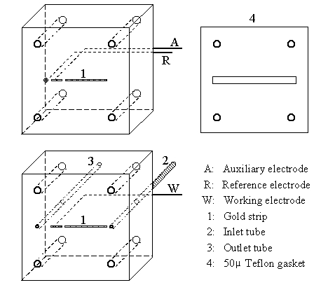
2.2. Fill a 1 ml syringe with the buffer or ACSF that you are going to use in the experiment and inject some of the solution into the inlet and outlet tubes to make sure that there is no blockage (Fig. 1). This step is not necessary for the first experiment, but it is recommended after each subsequent experiment.
2.3. Holding the block containing the inlet and outlet tubes, with its internal surface upward and horizontal, place a large drop of the solution on the surface and then arrange the PTFE gasket. Make sure that the triangular notch near the corner of the gasket is close to the dark triangular mark near to the corner of the block on the side surface. Move the gasket gently until the liquid has spread over the whole surface under the gasket.
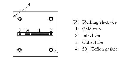
2.4. Under a stereomicroscope, adjust the position of the gasket to ensure that the gold strip and the platinum electrode are within the slot in the gasket, as should be the inlet and outlet tube openings (Fig. 2).
-
| Figure 1: 3-D diagram of the biosensor, showing the auxiliary/reference electrode block (top), the working electrode block (bottom), and the gasket. |
-
| Figure 2: Diagram illustrating the correct positioning of the Teflon gasket on the inner surface of the working electrode biosensor block. Note the triangular notch near the bottom right corner of the gasket, matching the dark triangular mark on the side of the block. |
3.2. Insert the 4 screws into their holes.
3.3. Bring the two blocks close to each other and screw in all 4 screws part of the way.
3.4. Push the two blocks gently into contact with each other then lightly tighten the 4 screws.
3.5. Fully tighten all 4 screws.
Fill a 1 ml syringe fitted with a blunt needle with perfusion medium. Insert the blunt needle into the rubber connector covering the end of the outlet tube, and inject firmly some of the perfusion medium. The solution should exit from the inlet tube as a small jet. Repeat this operation a couple of times. Before withdrawing the needle, make sure that there is a small drop of liquid on the tip of the inlet tube. This should ensure that no air is sucked back when the needle is withdrawn.
5. Connection of the potentiostat and the input line
The working electrode is located in the block containing the inlet & outlet tubes. This, together with the reference and auxiliary electrodes can now be connected. Before connecting the input line to the inlet tube, make sure that all the air has been expelled from it. It is advisable to have a small drop of solution at the tip of the input line before making the connection.
6. Perfusing and poising the biosensor
6.1. The working electrode should be poised at 0.6 V relative to the reference electrode. Set the rate of perfusion at the flow rate to be used during the experiment. Then, with the potential set at +0.6 V, switch on the potentiostat and apply this potential to the electrode system.
6.2. The biosensor should be poised for about 2 hours before connection to the outlet of the dialysis probe or any other experimental system, by which time the residual current should have gone down to a few nA. It is also advisable to repeat step 4 and purge the biosensor of air before connection to the outlet of the dialysis probe or any other flowing solution to analyse.7. Calibration
At the end of the experiment the biosensor should be calibrated with a 20 ?M glutamate solution. The syringe to be used for holding this solution should have been sterilised with absolute alcohol and then rinsed with distilled water. The calibrating solution should also be sterilised by filtration (Micropore filter 0.2 ?). This should avoid the problem of contamination of the biosensor by microorganisms.
8. Dismantling and storage
Before disassembling the biosensor, it is advisable to perfuse it until all trace of glutamate have been eliminated. This will also enable one to obtain a final baseline.
8.1. Switch the potentiostat to standby and disconnect the cable.
8.2. Disconnect the perfusion line.
8.3. Undo all 4 screws and separate the two halves of the biosensor.
8.4. Remove the gasket and place it between the polycarbonate strips.
8.5. Inject some air into the inlet and outlet tubes and, using the corner of a piece of tissue paper, remove the resulting drops of solution. Alternatively, inject a little distilled water into the inlet and outlet tubes but try to avoid getting the water on the enzyme. The purpose of this procedure is to avoid the salts from the perfusion medium being deposited inside the tubes when the solution dries out. As the diameter of the tubes is only about 0.1 mm, these salt deposits can easily cause a blockage.
8.6. Place the biosensor in its plastic box and keep refrigerated (4oC).
9.2. Another cause for current fluctuations is the presence of air in the biosensor. This can be corrected by flushing the biosensor with the perfusion medium (see 4.).
9.3. Tube blockage is often due to salt deposition in the tip of the tube at the surface of the biosensor. This can sometimes be corrected by placing a drop of distilled water on the tip of the tube where it opens into the biosensor. If, after about 15 minutes, this has not corrected the problem, the biosensor should be returned for the tube to be replaced.
| Applied Neuroscience |